| Urban | River | Medium-cost | Pluvial flooding | |
| DESCRIPTION | |
| Measures
|
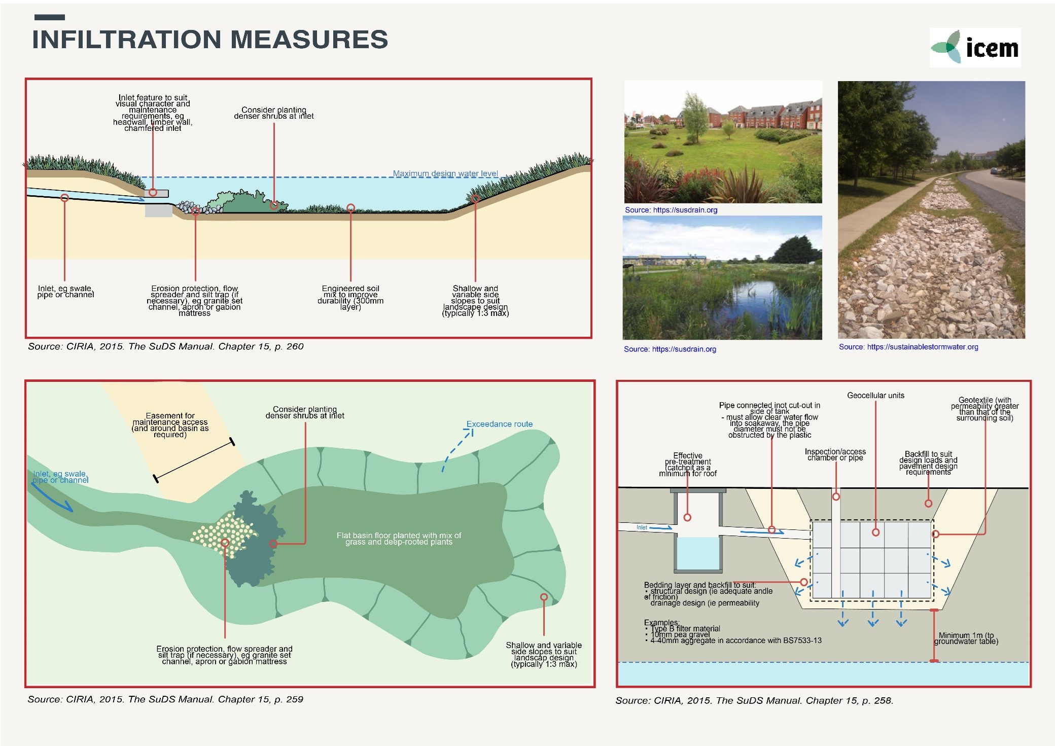
Infiltration zones are shallow excavated structures filled with permeable materials such as gravel or rock to create an underground reservoir. They are designed to hold stormwater runoff within a sub-surface trench and gradually release it to the surrounding soil and groundwater system. Runoff volumes and peak discharges from impervious areas are reduced by capturing and infiltrating the flows. They are generally positioned as the final element in a WSUD system and should not be located in steep or unstable areas.
Infiltration practices capture and temporarily store runoff before allowing it to infiltrate into the underlying soil over a period of 2 days. Infiltration can be used to: ● Partially or wholly manage the first 2.5 centimeters of rainfall on-site; ● Reduce pollutant loads to meet water-quality targets; ● Meet partial or full storage requirements for local stormwater detention standards. |
| Location | Infiltration zones are suitable for residential areas, commercial/industrial areas and housing estates and any areas that are heavily paved. They can also be integrated into the landscape of existing residences, offices, gardens, pocket parks, and large public parks. They are limited to fairly small catchments and due to the potential for clogging they should not be used for sites with fine particulate soils. |
| Design options and performance | Design criteria for infiltration zones are highly specific to rainwater intensities, local soil conditions and available space. They function best when high-infiltration soil types are present (sand or mildly reactive clays). Areas with highly reactive clay soils are not well suited to these systems. To protect nearby footings, slabs and other structures from cracking due to movement, the slope of the natural ground should not exceed 1 in 10, the depth to rock should be 1.2 m or greater and the groundwater table should be permanently below 1.5 m from the ground surface. To avoid clogging, pre-treatment of water for the removal of debris and sediment should be provided. Pre-treatment measures include leaf filters for roof runoff, sediment sumps, vegetated swales, bioretention systems or sand filters for surface runoff. |
| Feasibility criteria
|
Site topography: infiltration should be located on relatively flat areas of sites. Practices are best applied when the grade of the area immediately adjacent to the infiltration practice within 4-6 meters is greater than 1% and less than 5%. For sites with steep grades, infiltration should be split into multiple cells with adequate conveyance between the cells to take advantage of relatively flat areas.
Contributing to the CDA area: the maximum contributing drainage area (CDA) to an individual infiltration practice should be less than 0.8 hectares although smaller CDAs are recommended. Watershed runoff area. Collecting watershed runoff area of 0.4 ha and greater. The CDA should be as close to 100% impervious as possible. Micro-scale infiltration practices can also be designed for individual rooftops or other small areas of impervious cover. Setback: Infiltration practices should not be hydraulically connected to structure foundations or pavement, to avoid harmful seepage. Setbacks to structures vary based on the CDA of the infiltration practice: ● 20-240 square meters: 1.5 m if down-gradient from the building; 8 meters if up-gradient. ● 240-2000 square meters: 3 m if down-gradient from the building; 15 meters if up-gradient. ● 2,000-100,000 meters: 8 m if down-gradient from the building. Pre-treatment: One of the following techniques must be installed to pre-treat the inflow in every infiltration facility: ● Grass filter strip (minimum 6 m) and only if sheet flow is established and maintained ● Grass channel ● Forebay (minimum 25% of the design volume) ● Gravel diaphragm (minimum 0.3 m deep and 0.6 meters wide and only if sheet flow is established and maintained) ● Sand filter cell. For pre-treatment structures at the edge of pavement (e.g., grass filter gravel diaphragms, flow splitters), there must be a 5-10 cm drop from the edge of pavement to the top of the or stone in the pre-treatment structure. This is to prevent accumulation of and subsequent clogging at the point where runoff is designed to pre-treatment structure. If the infiltration practice serves a contributing drainage area (CDA) more than 2,000 square meters, a forebay or sand must be used for pre-treatment. The maximum depth of water in the basin should not typically exceed 2 m in the most extreme design event. Areas above the normal high-water elevations of the basin should also be sloped towards the basin to allow adequate drainage. The basin base can also be provided with a layer of engineered soil or underdrains to maintain a firm and dry surface. The recommended length/width ratio for online vegetated detention basins is between 3:1 and 5:1. Technical design: Infiltration systems consist of a shallow excavated trench, soakage well or tank, designed to retain a certain volume of stormwater runoff. The stored water permeates into surrounding soils, significantly reducing runoff volumes, having provided a means for treated runoff to recharge local groundwater aquifers and, in turn, surface water resources. Several different types of infiltration systems are available to the designer, each of which suits different sites and applications. These are: ● Infiltration trenches; ● Infiltration basins; ● Soakage wells or pipes; ● Permeable pavement; ● Infiltration swales. Soil media: n/a Soil slope: Maximum slope is 1:10 Surface cover: n/a Materials: There are various types of infiltration systems and materials are specific to the system selected. |
| Operation and maintenance | Infiltration zones need regular maintenance to ensure that the correct infiltration rate is being maintained and for cleaning material that has become clogged. |
| Cost and benefits | Medium cost measure. Infiltration zones can significantly reduce both runoff rates and volumes and reduce the pollutant load discharged to the receiving bodies. They can easily be included in landscape planning and fit well beside roads. |
| Design solution
|
Infiltration zones are shallow excavations usually in the form of basins or trenches, which are filled with rubble or stone to create temporary subsurface storage of stormwater runoff. The natural capacity of the ground to store and drain water is thus enhanced and the infiltration basins or trenches allow water to exfiltrate into the surrounding soils from the bottom and sides of the trench. Infiltration reduces both runoff rates and volumes and can significantly reduce the pollutant load discharged to the receiving water bodies. The shape of the trenches or basins is very flexible so they can easily be accommodated into the design of site landscapes and along road margins. |
| Environmental performance | Infiltration zones are very effective in reducing peak flows entering the stormwater system and removing pollutants from stormwater runoff. They can be planted with trees, shrubs and other plants, improving their visual appearance and providing habitats for wildlife. Infiltration zones increase soil moisture content and help to recharge groundwater, thereby mitigating problems of low river flows. |
| Sources | ● CIRIA. 2015. The SuDS Manual. Chapter 13, Infiltration Systems.
● Melbourne Water,.2005. WSUD Engineering Procedures: Stormwater. ● Pennsylvania Stormwater, 2006. Best Practice Manual – Chapter 6. ● Susdrain, not dated. Delivering SuDS – Infiltration overview. |
Originally developed under the ADB ‘TA-9417 VIE: Secondary Green Cities Development Project – Output 2: Demonstrated sustainable and resilient development in Hue, Ha Giang and Vinh Yen’. Adapted for the UN-CTCN project ‘Climate risk assessment for subnational adaptation and establishment of a local climate information system for climate change adaptation (LISA) in Cambodia’.